TM 5-5420-202-20-3
BRAKE CONTROL HOUSING REPAIR (Sheet 10 of 14)
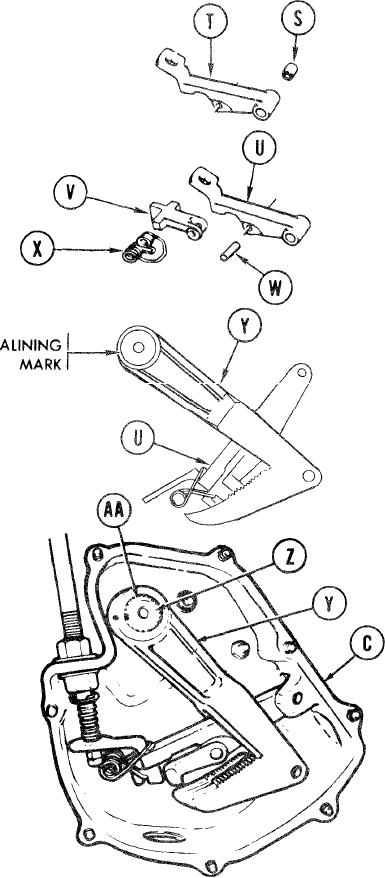
17. Using vise and brass jaw caps press bearing (S) into lever
(T).
18.
Position lever (U) assembly on pawl (V)
and start pin (W) through pawl and lever
assembly. Position in vise and press
pin through.
Place large loop of spring (X) over end
19.
of lever assembly (U) and other loop
over end of pawl (V).
Insert lever assembly (U) with its attached parts
20.
through cut out in lever (Y).
NOTE
When installing lever (Y) in
housing assembly (C) make
sure alining mark (dot) on
lever (Y) is in line with wide
slot in shaft (Z).
21.
Slide lever (Y) with its assembled parts on
shaft (Z).
Using retaining ring pliers, install snap
22.
ring (AA) in groove of shaft (Z).
TA249457
Go on to Sheet 11
13-73

