
TM 5-5420-202-20-3
STEERING CONTROL CLEVIS AND STUD REPLACEMENT (Sheet 3 of 3)
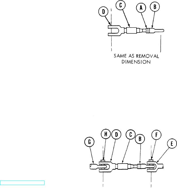
INSTALLATION:
1.
Using 9/16 inch wrench, install jamnut
(A) and rod end (B) on rod (C).
Using steel tape, measure between center
2.
of hole in rod end (B) and center of
hole in clevis (D).
3.
Using 9/16 inch wrench, turn rod end
(B) to obtain same dimension recorded
at removal.
4.
Using torque wrench and crowfoot adapter,
tighten jamnut (A) against rod end (B)
to a minimum torque of 16-18 lb-in.
(21.7-24.4 N.m).
5.
Aline rod end (B) in link (E).
6.
Using 9/16 inch wrench, install bolt
(F) in link (E).
7.
Aline rod end (G) in clevis (D).
8.
Using 9/16 inch wrench, install bolt
(H) in clevis (D).
Test operation of clevis (D) and rod (C)
9.
linkage (TM 5-5420-202-10).
TA249641
End of Task
15-18