
TM 5-5420-202-20-3
LINK ASSEMBLY REPLACEMENT (Sheet 3 of 3)
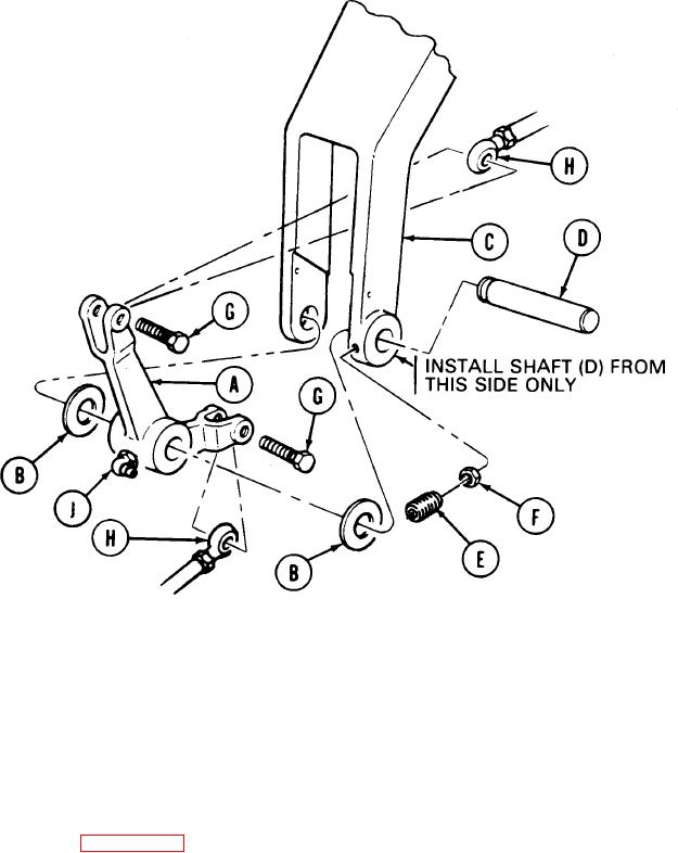
INSTALLATION:
1.
Position link (A) and two washers (B) mounting bracket (C).
2.
Using hammer, drive shaft (D) through bracket (C), washers (B), and link (A) until shaft
(D) is flush with bracket (C).
3.
Using allen wrench, install setscrew (E) and nut (F) into bracket (C). Using 7/16 inch
wrench to hold nut (F), tighten setscrew (E) into groove of shaft (D). Tighten nut (F)
against bracket (C).
4.
Using 9/16 inch socket, install two bolts (G) through link (A) and rod end bearings (H).
Using torque wrench, tighten bolts (G) to 15-30 lb-ft (22-27 N.m).
5.
Using 3/8 inch wrench, install grease fitting (J) into link (A).
6. Install transmission shroud (page 9-6).
7.
Install top deck (page 16-23).
TA249646
End of Task
15-23