TM 5-5420-202-34
ACCELERATOR CONTROL LINKAGE ASSEMBLY REPAIR (Sheet 10 of 13)
8.
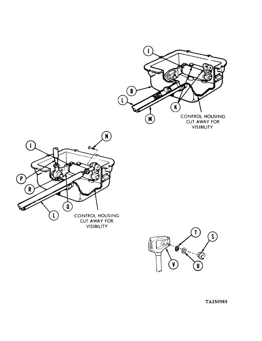
Using 1/2 inch socket, install two screws
and two lockwashers (K) holding lever
assembly (J) to control housing (B).
Install tube assembly (L) through shaft
9.
(M) into control housing (B).
10.
Position tube assembly (L) into mating
clevis of lever assembly (J).
Using 7/16 inch wrench, install bolt (N)
11.
to hold tube assembly (L) to lever assembly
(J).
12.
Position connecting link (P) into remaining
rod end clevis (Q) of lever assembly (J).
13.
Using 7/16 inch wrench, install bolt (R)
to hold connecting link (P) to rod end clevis
of lever assembly (J).
14.
If bearing (S) is being installed, insert
new preformed packing (T) and new washer (U)
into riser housing (V).
Go on to Sheet 11
4-108


