TM 5-5420-202-34
ACCELERATOR CONTROL LINKAGE ASSEMBLY REPAIR (Sheet 9 of 13)
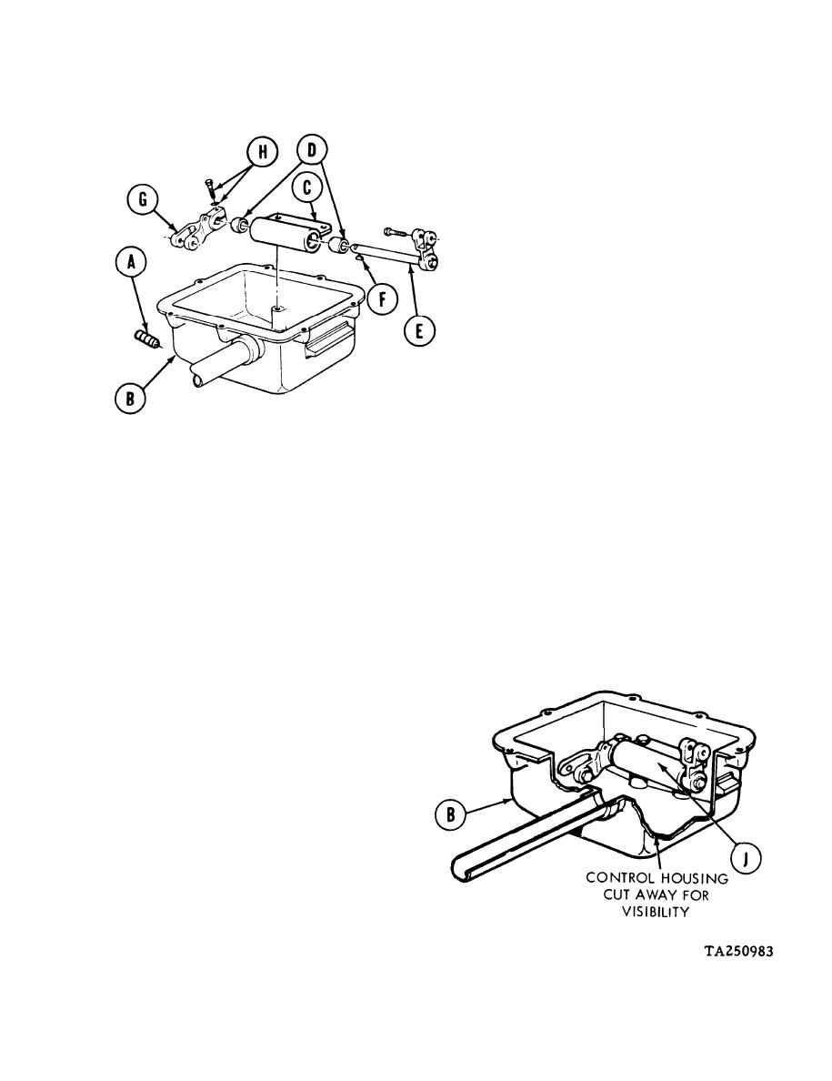
ASSEMBLY:
1.
Using socket head screw key, install
drain plug (A) into control housing (B).
2.
Push housing (C) with two bearings (D)
onto clevis with shaft (E). Line up scribe
marks on housing (C) and clevis with
shaft (E).
3.
Using hammer, install new woodruff
key (F) into clevis with shaft (E).
4.
Push clevis rod end (G) onto clevis with shaft (E). Line up reference marks on housing
(C) and clevis rod end (G).
5.
Line up reference marks on housing (C) and clevis rod end (G) and clevis with shaft (E).
Install clevis rod end (G) on clevis with shaft (E).
6.
Using 7/16 inch wrench, install screw and lockwasher
(H) into clevis rod end (G).
7.
Install clevis with shaft (E), two bearings
(D), housing (C), and clevis rod end (G)
into control housing (B) as a complete
lever assembly (J).
Go on to Sheet 10
4-107


