TM 5-5420-226-20-2
CYLINDER HEAD AND OIL PAN DRAIN TUBES (LEFT AND RIGHT) REPLACEMENT
(sheet 4 of 4)
8.
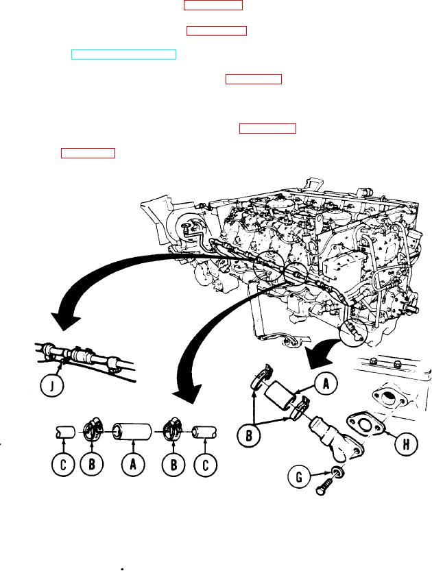
P o s i t i o n two bolts and washers (G) through lower drain tube end and place new g a s k e t
(H) over bolts.
U s i n g 1/2 inch socket, tighten two bolts and washers (G) to engine.
9.
10.
Using screwdriver, tighten 16 clamps (B) on hoses (A) and (C) on each end of
l o w e r drain lines assembly.
11.
H o l d i n g nut with 3/8 inch wrench and using screwdriver, connect four fuel line c l a m p s
(J) to oil drain line.
12.
I n s t a l l left oil "cooler frame and brackets (page 6-131) (as required).
13.
I n s t a l l right oil cooler frame and brackets (page 6-121) (as required).
14.
R e p l e n i s h engine oil (LO 5-5420-226-12).
15.
C o n n e c t powerplant test (ground hop) equipment (page 5-25).
16.
S t a r t engine and check for leaks.
17.
D i s c o n n e c t powerplant test (ground hop) equipment (page 5-25).
18.
I n s t a l l powerplant (page 5-14).
End of Task
TA1076O5
6-138

