TM 5-5420-226-20-3
SHIFTING CONTROL AND RELATED PARTS REPAIR AND REPLACEMENT (Sheet 9 of 14)
6.
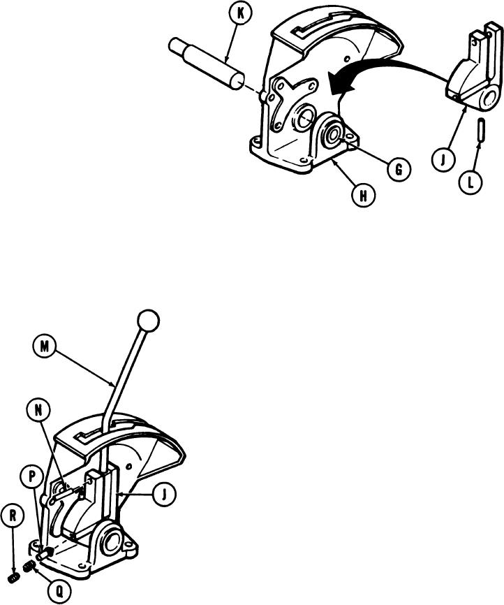
Position pivot (J) on base assembly(H).
Aline hole in pivot (J) with hole in base
7.
assembly (H).
8.
Using hammer and wooden block, insert shaft (K) into base assembly (H) through pivot
(J) and into bearing (G). Use care not to damage bearing (G).
Using 1/8 inch tapered steel drift, aline shaft pin hole with pivot pin hole.
9.
10. Using hammer and 3/4 inch brass drift, install pin (L).
11.
Position control rod lever (M) thru pivot
(J).
12.
Using hammer and 1/4 inch punch, install
pin (N).
13.
Using flat-tip screwdriver, install plunger (P),
spring (Q), and adjuster (R).
Go on to Sheet 10
TA169012
11-10

