
TM 5-5420-227-24
OVERHEAD CYLINDER HOSE ASSEMBLIES (CL, CM, CN, AND CO) AND HYDRAULICS
REPLACEMENT (Sheet 6 of 8)
10.
Using care to prevent damage, clamp
--
-.
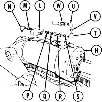
relief valve (L) in vise.
11.
Using 1-1/8 inch wrench, install
nipple (M) into relief valve (L).
Using 12 inch adjustable wrench, install
120
elbow (N) onto nipple (M).
13.
Using 1-1/8 inch wrench, install nipple (P) into relief valve (L).
14.
Holding nipple (P) with 1-1/8 inch wrench, use 1-3/8 inch wrench to install bushing (Q)
onto nipple (P).
NOTE
Install regulator (R) with flow arrow pointing away from relief valve (L).
Holding bushing (Q) with 1-3/8 inch wrench, use 15 inch adjustable wrench to install
15.
regulator (R) onto nipple (P).
16.
Holding regulator (R) with 15 inch adjustable wrench, use 1-3/8 inch wrench to install
bushing (S) onto regulator (R).
17.
Holding bushing (S) with 1-3/8 inch wrench, use 12 inch adjustable wrench to install
elbow (T) into bushing (S).
18.
Holding elbow (T) with 15 inch adjustable wrench, use 12 inch adjustable wrench to install
elbow (U) and collar (V) into elbow (T).
19.
Remove relief valve (L) and attached parts from vise.
20.
Using 12 inch adjustable wrench, install elbow (N) and attached parts in cap end of cylinder
(H).
210
Holding elbow (U) with 12 inch adjustable wrench, use 1-1/4 inch wrench to install hose
assembly (W) onto elbow (U).
Go on to Sheet 7
TA170350
3-124