
TM 5-5420-227-24
Section Ill. FILTER, HOSE ASSEMBLIES, AND ASSOCIATED HYDRAULICS
OVERHEAD CYLINDER HOSE ASSEMBLIES (CL, CM, CN, AND CO) AND HYDRAULICS
REPLACEMENT (Sheet 1 of 8)
PROCEDURE INDEX
PAGE
PROCEDURE
Removal
Installation
9/16 in. socket with 1/2 in. drive
TOOLS: 12 in. adjustable wrench
Ratchet with 1/2 in. drive
1-1/4 in. open end wrench
Vise
1-1/8 in. open end wrench
1-3/8 in. open end wrench
15 in. adjustable wrench
SUPPLIES:
Drip pans
Pencil
Pipe tape (It em 19, Appendix D)
Rags (Item 12, Appendix D)
Masking tape (Item 18, Appendix D)
Caps and plugs (assorted sizes)
Lockwashers (8 required)
Preformed packing (3 required)
REFERENCE:
PRELIMINARY
PROCEDURES:
Remove overhead cylinder armor (page 3-217)
Remove front fixed and moveable hose armor (page 3-
R e l i e v e hydraulic pressure (page 3-65)
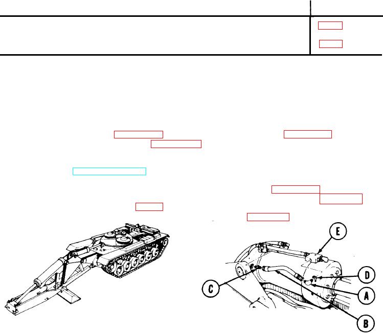
REMOVAL:
NOTE
Use rags and drip pans to catch excess hydraulic fIuid. Use masking tape to
tag lines for installation. Cap or plug all lines and fittings as disconnected.
1.
Holding elbow (A) with 12 inch adjustable wrench, use 1-1/4 inch wrench to disconnect
hose assembly (B) from elbow (A).
2.
Holding adapter (C) with 1-1/8 inch wrench, use 1-1/4 inch wrench to remove
hose assembly (B) from adapter (C).
3.
Using 12 inch adjustable wrench, remove elbow (A) and collar (D) from relief valve (E).
TA170345
Go on to Sheet 2
3-119