
TM 5-5420-227-24
SCISSORS CYLINDER HOSE ASSEMBLIES (CF1, CF2, CG, Cl, AND CJ) AND HYDRAULICS
REPLACEMENT (Sheet 7 of 12)
INSTALLATION:
NOTE
Remove all caps and plugs as necessary during installation. Before installa-
tion, use pipe tape on all male threads. Start tape on second thread so tape
will not enter hydraulic system.
NOTE
Procedure for installation of right side components and left side compo-
nents is identical. Right side shown.
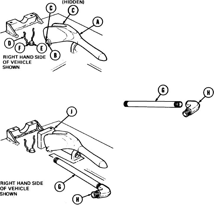
1.
Place handle (A) in position.
using hammer, tap pin (B) into position.
2.
3.
Using long round nose pliers, install two
cotter pins (C) to secure pin (B).
4.
Place spring retainer (D) into position.
5.
Using 3/8 inch socket, install screw (E) and lockwasher (F) securing spring retainer (D).
6.
Holding nipple (G) with pipe wrench, use 12
inch adjustable wrench to install elbow (H).
7.
Manually install nipple (G) with elbow (H)
in position.
8.
Manually install clamp (J) in position on
nipple (G).
TA170365
Go on to Sheet 8
3-139