
TM 5-5420-227-24
ACCESSORI ES CON T ROL BOX REPAI R (She e t 6 of 8 )
N OT E
Apply silic one c om pound t o
a ll rubbe r e le c t ric a l c onne c -
t ors be fore inst a lla t ion.
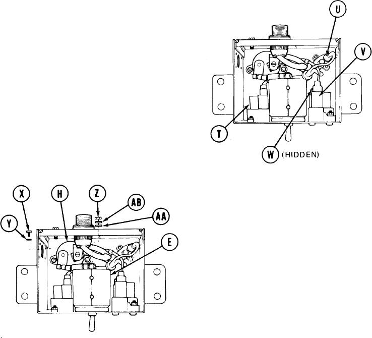
11.
Manually connect electrical connector
(CKT 137) to circuit breaker (T).
12.
Manually connect electrical connector
(CKT 465) to circuit breaker (U).
13.
Manually connect electrical connector
(CKT 894) to circuit breaker (V).
14.
Manually connect electrical connector
(CKT 625) to circuit breaker (W).
15.
Place one end of cable assembly
(CKT 159) on remaining terminal Of
circuit breaker (H).
16.
Using flat-tip screwdriver, install
screw (X) and new lockwasher (Y) to
circuit breaker (H).
17.
Place remaining end of cable assembly
(CKT 159) on rear of switch assembly (E).
18.
Using 7/16 inch wrench, install nut (z),
flat washer (AA), and new lockwasher (AB)
to switch assembly (E).
Go on to Sheet 7
4-13