
TM 5-5420-228-24
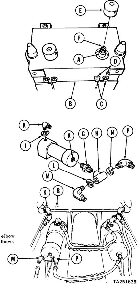
EJ ECT I ON CY LI N DER REPLACEM EN T (LEFT ) (She e t 3 of 4 )
INSTALLATION:
Position ejection cylinder (A) in tongue (B).
1.
Manually install two screws (C) and
2.
lockwashers (D) in bottom of tongue (B)
to secure ejection cylinder (A).
Using 1-1/2 inch wrench, tighten two
3.
screws (C) and lockwashers (D).
Manually start plug (E) on threads
4.
of cylinder rod (F).
Using punch in hole of plug (E),
5.
tighten plug (E) while holding
cylinder rod (F) from turning
with screwdriver.
NOTE
Before installation, use pipe tape on all
male pipe threads. Start tape on second
thread so tape will not enter hydraulic sys-
tem. Re m ove a ll c a ps a nd plugs a s ne c e s-
sa ry during installation.
Using 3/4 inch wrench, install
6.
nipple (G) in ejection cylinder (A).
Using 3/4 inch wrench to hold nipple (G),
7.
use adjustable wrench to install tee (H)
on nipple (G).
Manually place collar "CA" (J) on elbow (K),
8.
collar "CC" (L) on elbow (M), and collar "CB"
(N) on elbow (P).
Manually install elbow (K) on ejection
9.
cylinder (A) and elbows (M, P) on tee (H).
Using adjustable wrench, tighten
10.
(K) on ejection cylinder (A) and e
(M, P) on tee (H).
Go on to Sheet 4