TM 5-5420-228-24
HYDRAULIC PUMP REPAIR (Sheet 9 of 11)
NOTE
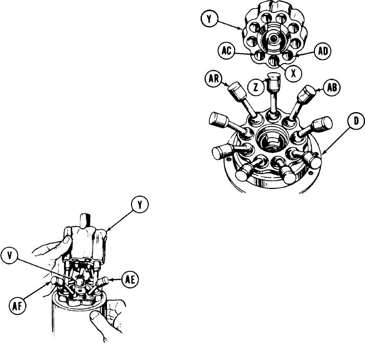
Cylinder bore (X) that is in line with cylinder
b l o c k (X) y retainer slots is No. 1 cylinder
b o r e . Piston (Z) that is in line with drive
s h a f t ( 0 ) r e t a i n e r s l o t s i s N o . 1 piston.
Remove protective caps as necessary.
16.
Insert No. 1 piston (Z) in No. 1 cylinder
bore (X).
17.
Insert two pistons (AA, AB) closest to
No. 1 position (Z) in their cylinder bores
(AC, AD).
18.
Continue inserting pistons, first on one
side of No. 1 piston, then on other side,
until only two pistons remain (AE, AF)
uninstalled.
19.
Tilt cylinder block (X) carefully back and
slip rear knuckle (V) into cylinder block
retainer with grooved end up.
Tilt cylinder block (Y) forward and slide remaining knuckle (V) into remaining retainer
20.
slot.
21.
Install two remaining pistons (AE,AF).
22.
Push cylinder block (Y) straight down to check installation. Action should be smooth
and springy.
Go on to Sheet 10
TA251700
4-50

