TM 5-5420-278-10
0011 00
0011 00-2
INTERIOR BAY CONTROLS AND INDICATORS (Contd)
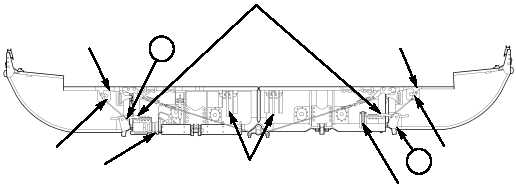
OUTER PONTON LOCKS — There are two outer ponton locks at each end
of the IRB-I. Each is engaged by inserting the end of a T-wrench (refer to
Item 2, WP 0070 00) into a hole in the bellcrank; the bellcrank is accessed
through an opening at the end of the outer ponton walkway. The bellcrank is
rotated until the lock/release lever is visibly engaged on the striker plate,
located on the adjacent inner ponton.
D
UPPER COUPLING, LONGITUDINAL — There are two identical upper
couplings and two receptacle blocks at each end of the IRB-I. The upper
coupling consists of a spring-loaded lever mounted in a receptacle block at
each end of both inner pontons. A receptacle block is adjacent to each upper
coupling. The upper coupling is used for bay-to-bay connection; when two bays
are in position to be joined longitudinally, the two upper couplings on each
bay are manually closed by placing them in the receptacle blocks of the
opposite IRB-I or IRB-R.
UPPER COUPLING, TRANSVERSE — There are two identical upper
couplings, each located on the inner pontons, that consist of a spring-loaded
lever mounted in a receptacle block. When the bay is unfolded, both upper
couplings are manually closed by placing them in the opposite receptacle block
of the adjacent inner ponton. They are both opened prior to IRB-I retrieval;
this is essential prior to lifting to prevent damage.
F
E
OPENING, OUTER
PONTON WALKWAY
OPENING, OUTER
PONTON WALKWAY
INTERIOR BAY (UNFOLDED)
HOOK LEVERS AND
STRIKE PLATES
BELLCRANK
BELLCRANK
D
D
FOLDLOCKS, OPEN
POSITION
TRAVEL LATCH,
LOCATING RECEPTACLE
TRAVEL LATCH LEVER,
OPEN POSITION