TM 5-5420-278-10
0030 00
0030 00-2
RAMP BAY TO INTERIOR BAY CONNECTION (Contd)
NOTE
Refer to WP 0011 00 for specific instructions on the use
of the coupling device.
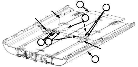
c. Using two coupling devices simultaneously, raise ramp bay (1) up until its
roadway surface is even with roadway surface of interior bay (4).
WARNING
Keep hands clear of space between bays when closing
longitudinal upper couplings, and do not place fingers
under couplings when closing them, or serious injury to
personnel may result.
NOTE
The upper couplings are closed when the levers are
fully down in the receptacle blocks of the adjacent bay.
d. When bays are together, close two longitudinal upper couplings (3) on ramp
bay (1) and two longitudinal upper couplings (3) on interior bay (4).
CAUTION
The top of lower lock-drive jackscrew will be 3/4 in.
(1.9 cm) below top surface of roadway when lower
lock-drive pin is fully engaged. Failure to comply may
result in equipment damage.
e. Install T-wrench on jackscrew (5) of lower lock-drive, and turn T-wrench
clockwise until lower lock-drive pin is fully engaged, then back out jackscrew
(5) one full rotation.
f. Repeat step e for opposite lower lock-drive.
NOTE
Perform steps g and h if either lower lock-drive pin
cannot be fully engaged. Failure to comply may result
in equipment damage.
g. Open pump access covers (2), set pump control levers to UP position, and
operate pumps while assistant turns T-wrench to engage lower lock-drive pins.
h. Set pump control levers to TRANSPORT/CROSSING positions, and close
pump access covers (2).
COUPLING DEVICE
T-WRENCH
COUPLING DEVICE
1
4
3
5
3
2
END OF WORK PACKAGE