TM 5-5420-278-10
0035 00
0035 00-30
BRIDGE ANCHORAGE (Contd)
INSTALLATION OF AN OVERHEAD CABLE ANCHORAGE SYSTEM (Contd)
d. Installing the Overhead Cable.
(1) Emplace anchor cables by mounting the cable reel on the near shore and tow the
free end of the cable across the river using a BEB. If the stream bottom is hard
and reasonably clear of shelf rocks and snags, this method is most effective. The
use of intermediate floating supports, in areas where a large number of potential
snags exist on the river bottom, may be of good use. Care must be taken when
using intermediate floats, particularly in rivers with a swift current, to ensure
that the boat can overcome the drag developed by towing the cable.
(2) Once the cable is ready for attachment to the deadman, place the cable under
the deadman and around it. If the cable cuts into the ground, place a log or
board under the cable at the outlet of the sloping trench.
(3) Measure and mark the initial sag distance from the point of support on each
tower. (Refer to figure 20.) Establish a line of sight between the marks.
Tighten the cable until its lowest point touches the line of sight. This
adjustment must be made before the bridge is connected to the cable. Tighten
cable clips frequently as more strain is placed on the cable when bridle lines
from the floats are attached. After the cable has been placed in service and is
under tension, tighten the cable clips again to compensate for any decrease in
cable diameter caused by the load and ensure equal distribution of load
between the clips.
(4) Use the cable clips to secure the cable. Attach these clips above the ground
for ease of tightening and maintenance.
e. Attachment of Bridle Lines. Once the overhead cable is secured, the bridle
line crew can begin connecting the bridle lines from each float to the overhead cable.
Bridle lines are normally 32 ft (9.8 m) long sections of 1-in. (2.5-cm) manila rope
and are attached to the pontons in the ponton assembly area. Use bridle line
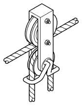
connectors (refer to figure 19) to attach the bridle lines to the overhead cable.
Figure 19. Bridle Line Connector


