TM 5-5420-278-24&P
0022 00
0022 00-6
NOTE
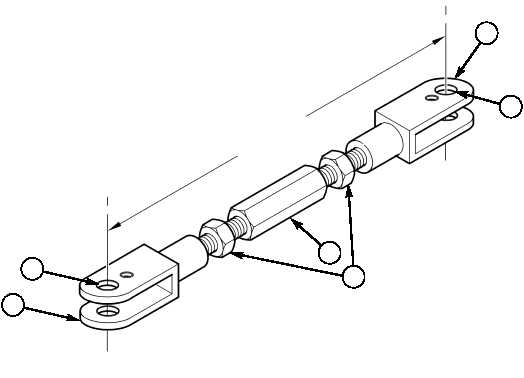
Free threads on turn buckle clevis ends must have the same
number of threads showing ± two threads.
14.
Loosen nuts (3) and pre-set turnbuckle (4) to 13.5 ±0.2 in. (343 ±5 mm) from center of holes (2) by
adjusting turnbuckle cleves ends (1). Do not tighten nuts (3) until turnbuckle (4) is installed.
WARNING
All personnel must stand clear during lifting operations. Ensure
ponton foldlock and travel latches are in good mechanical
condition and securely locked prior to lifting outer ponton. Failure
to comply may result in injury to personnel.
15.
Lift outer ponton (5) and install 3 x 4.7 x 10.8 in. (8 x 12 x 27.5 cm) block (6) in position under
connect link (7) and lower outer ponton (5) until turnbuckle clevis (1) aligns with hole in torsion bar
lever (8), and install turnbuckle clevis (1) on torsion bar lever (8) with pin (9), washer (10), and
screw (11). Remove block (6).
16.
Lower outer ponton (5) down on inner ponton (12) and install pre-stressing tool (13), flat edge
against deck overhang (14), on outer ponton (5) and adjust turnbuckle (4) until torsion bar lever (8)
aligns with pre-stressing tool (13) then tighten two nuts (15). Remove pre-stressing tool (13).
17.
Apply grease to lube fitting (WP 0016 00).
18.
Engage foldlock.
19.
Connect inner pontons (WP 0023 00).
20.
Install ramp bay on transporter (TM 5-5420-278-10).
TORSION BAR REPLACEMENT (Contd)
1
2
2
1
4
3
13.5 ±0.2 in.
(343 ±5 mm)