TM 5-5420-278-24&P
0022 00
0022 00-2
TORSION BAR REPLACEMENT (Contd)
REMOVAL
WARNING
All personnel must stand clear during lifting operations. Ensure
ponton foldlock and travel latches are in good mechanical
condition and securely locked prior to lifting outer ponton. Failure
to comply may result in injury to personnel.
NOTE
Removal and installation of right and left torsion bars are
performed the same way. Right side is shown.
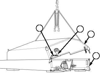
1.
Unlock foldlock (4), and lift outer ponton (3) from inner ponton (5) until preload tension on torsion
bar lever (2) is off turnbuckle (1).
2.
Remove screw (6), washer (7), and pin (8) from turnbuckle (1) and torsion bar lever (2), and slide
turnbuckle clevis (9) off torsion bar lever (2).
3.
Remove screw (22), washer (23), and washer (24) from torsion bar lever (2) and torsion bar (20).
4.
Install washer (24), washer (23), and screw (22) on torsion bar (20) finger tight.
5.
Mark position of torsion bar lever (2) on outer ponton (3), and remove torsion bar lever (2) from
torsion bar (20).
6.
Mark position of flange (15) and outer ponton (3), and remove eight screws (17), washers (16), and
torsion bar housing (14) from outer ponton (3).
NOTE
Note location and quantity of spacer(s) for installation.
7.
Remove screw (25) from torsion bar housing (14) and washer (12).
8.
Remove screw (10), washer (11), washer (12), and spacer(s) (13) from torsion bar housing (14) and
torsion bar (20).
9.
Push torsion bar (20) out of torsion bar housing (14).
NOTE
Perform step 10 if removing spacer from torsion bar.
10.
Using puller, remove spacer (21) from torsion bar (20).
11.
Remove O-ring (18) and lube fitting (19) from flange (15). Discard O-ring (18).
1
2
3
4
5
1
2
3
5