
TM-5-5420-279-10
2.3.1.5
When in the folded condition, the modules are 8 ft (2.447 m) wide (over the nibs) and
14 ft (4.302 m) wide when deployed. One end of the ramp module incorporates a
dowel and shootbolt arrangement along with a jaw configuration. This connection
system is common with the parallel modules.
2.3.1.6
The toe end of the ramp incorporates an aperture in which the end beam locates, it is
held by an upper fixed and a lower removable pin, which is locked by a twisting
action. Guide pads located within the aperture are used to align the lower holes of
the end beam and the ramp module.
2.3.1.7
With the end beam inserted, a continuous gutter is created onto which the approach
ramps are `hooked' to complete the end of bridge.
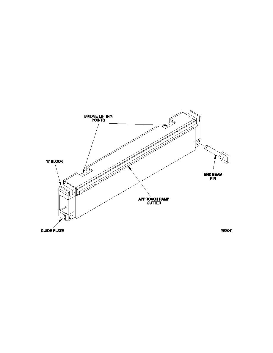
Ramp End Beam
Figure 2. 20 End Beam
2.3.2.1
The end beam is a rectangular welded box section, which is positioned in an aperture
at the toe end of each ramp module. It includes bridge lifting points through which the
forward carriage straps are routed and also provides mounting for the bridge
approach ramps. Fixed pins within the aperture of the ramp module locate on the end
beam as the ramp module is lowered down onto it and side guide pads aid alignment
of the lower holes. The end beam is secured to the ramp module at its lower edge by
insertion of twist-to-lock pins.
