
TM-5-5420-279-10
NOTE
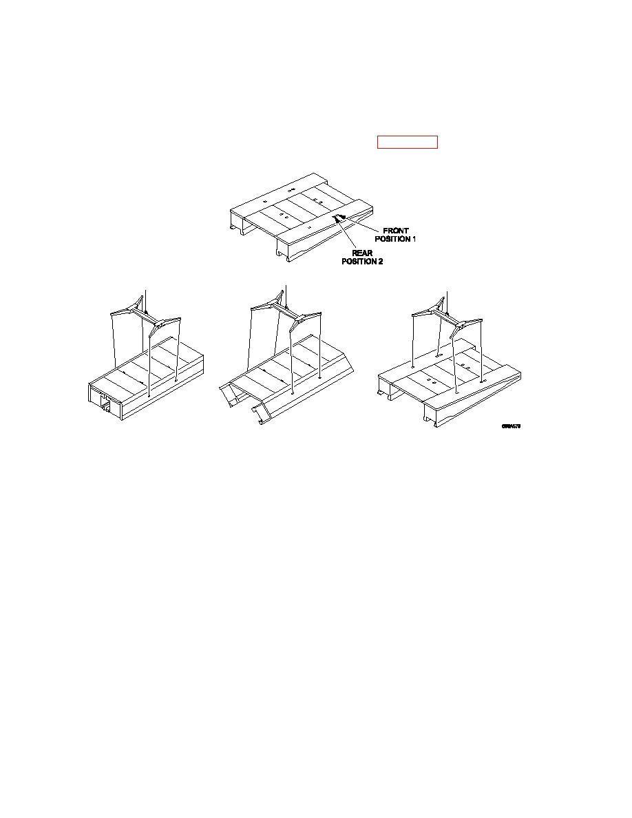
The module lifting beam must be positioned so that the main beam runs across the panel.
The front lifting sling of the bridge module lifter MUST be fitted to the rear position (POSITION
2) of the two front end lifting slings on the ramp module (see Figure 3. 31), this is to enable the
ramp module to be balanced as the end beam is not fitted at this stage.
3.9.4.4
Attach tag lines to one front handle and through the end beam pin hole to assist in
controlling the ramp module when lifting operations commence. If building from the right
attach both tag lines to the right-hand side, if building from the left attach tag lines to left-
hand side.
NOTE
Make sure the opening slings are in the correct position when lifting the ramp module with or
without the ramp end beam installed. When the ramp module DOES NOT have the end beam
fitted, then the REAR (position 2) attachment position MUST be used. When the ramp module
has an end beam fitted, due to the extra weight the center of gravity moves forward, the
FRONT (position 1) attachment position MUST be used.
3.9.4.5
Operate the lift controls on the crane and lift the ramp module.
3.9.4.6
As the ramp is lifted, it will open to its working position.
3.9.4.7
Disconnect the bridge module lifting beam from the POSITION 2 lifting points on the
outboard sides of the far bank ramp module ramp panels.
3-64
