TM-5-5420-279-10
4.6.1.18
Continue to extend the stabilizer leg hydraulic cylinders and lower both A-frame
stabilizer bearing pads to the ground, lifting the slide frame clear of the chassis until
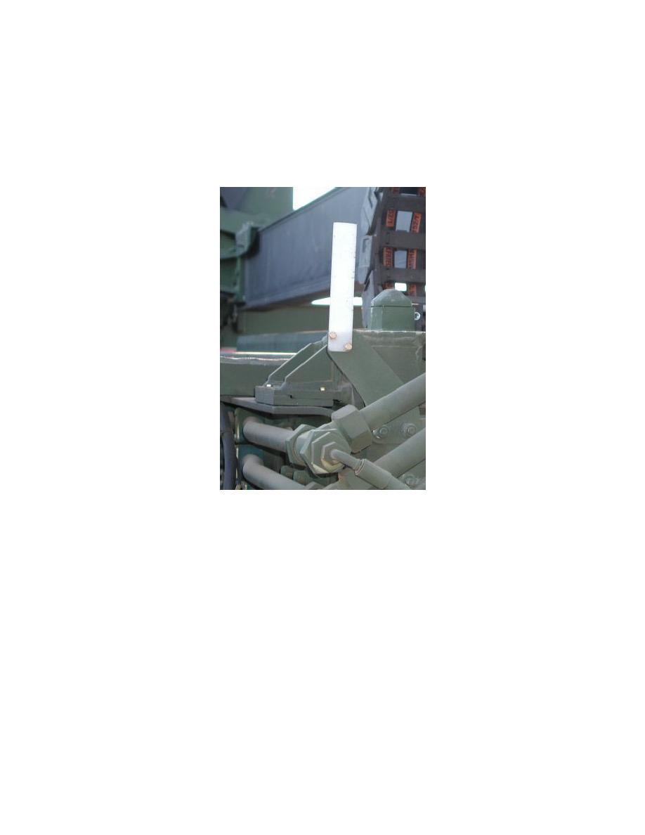
the twist lock blocks are clear of the white chassis positioning aids on the chassis.
NOTE
Ensure that both stabilizer pins are in the same number hole on each leg and that both
twist lock blocks are level with or above the white chassis positioning aids.
Chassis Positioning Aid
4.6.1.19
Insert the pins in the highest pinhole position available from the inside out and lock in
place with the R clip in the outermost hole of the pin.
4.6.1.20
Lower the A-frame onto the pins.
4.6.1.21
Operate the switches on the tail lift pendant to position tail lift so that it will clear any
obstructions on the ground and pass under the A-frame lower cross member, when
the vehicle is driven forwards.
4.6.1.22
Secure tail lift pendant and its umbilical cable on tail lift to prevent damage during
slide frame deployment.
NOTE
Do not level the A-frame at this stage or the slide frame could be damaged.
4-23


