TM-5-5420-279-10
4.4.1.9
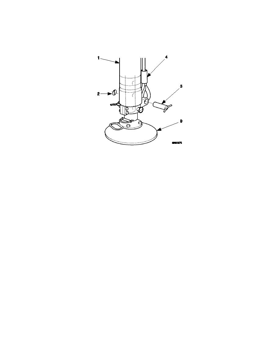
Remove the retaining clips (2) and the pins (3) and disconnect the wire rotation cable
(4) from the bottom of the crane stabilizer legs (1). Refit the pins (3) and retaining
clips (2).
Wire Rotation Strap Pins and Clips
4.4.2
Securing Far Bank Support for Transport to Build Site
4.4.2.1
Ensure all pins are fitted to the A-frame hinge points in preparation for moving the
launch vehicle to the bridging site.
4.4.2.2
Ensure that the launch vehicle is secured for movement to the bridging site and
ensure tail lift pendant is removed and stowed.
4.4.2.3
Close the interface enclosure door.
4.4.2.4
In the vehicle cab, switch the four position switch to position 1.
4.4.2.5
Ensure the PTO disengages.
4.4.2.6
Select gear and release parking brake.
4.4.2.7
Deploy the launch vehicle to the bridge site.
4-19


