TM-5-5420-279-10
4.5 BRIDGE DEPLOYMENT
NOTE
When an item is on the vehicle or launcher and is referred to as front or rear, left or right,
the cab is taken as the front of the launch vehicle, all references are taken as if personnel
are looking forward towards the cab. Therefore, if the left hand side A-frame leg is being
discussed, the A-frame leg on the launch vehicle's left hand side is the item being
described.
When referring to the launch beam the front of the beam is to be taken as the far bank and
the rear is taken as the near bank, it follows therefore that the rear carriage is the home
bank carriage and the front carriage is the far bank carriage.
Build Site Initial Vehicle/Flatrack Location
4.5.1.1
Drive the partially deployed launch vehicle onto the site.
4.5.1.2
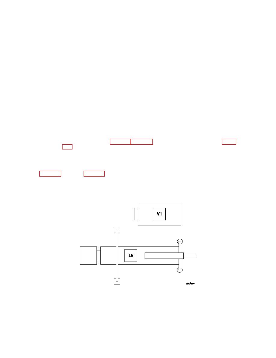
Reverse launch vehicle with its left hand wheels along the center alignment line until
the center of the A-frame stabilizer pads line up with the set back mark on the
alignment line (refer to Chapter 1 Para 1.2.9, Site Marking for Bridge Build and Figure
NOTE
The set back distance "A" is variable, dependent on gap, and should be calculated from
4.5.1.3
Drive vehicle V1 with V1 load onto the bridge site, reverse it with its left-hand wheels
along the right hand tire alignment line placing the flatrack at its position along the
pre-marked line. (Rear right hand side of launch vehicle).
Positions of Flatracks
4.5.1.4
Drive vehicle V3 with LVT load onto the site and reverse it with its left-hand wheels
along the left hand tire alignment line placing the flatrack at its position along the pre-
marked line (rear left hand side of launch vehicle).


