
TM-5-5420-279-10
Insert the pins to connect the 1st parallel module to the far bank ramp module and
4.9.3.14
secure the pins with the R clips. The pins on the outside of the bridge being inserted
from the outside in and the inner pins from the inside out.
4.9.3.15
Disconnect the tag line at the rear of the parallel module.
NOTE
Providing the four slings are slack, the guide system on the parallel modules will ensure
correct alignment for pin insertion.
If the pins can not be inserted, the weight of the module may be taken by the crane until
the pins can be inserted. If connection problems persist disconnect all pins and
shootbolts and rotate the panel through 180 degrees so that the opposite end may be
connected.
4.9.3.16
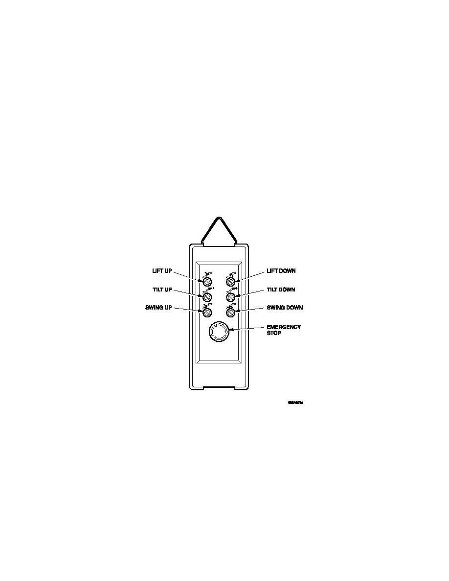
On the tail lift pendant operate the LIFT DOWN switch, and lower the tail lift platform
and the pinning operatives clear of the path of the parallel module.
Tail lift Hand Control
Disconnect the bridge module lifter from the 1st parallel module and instruct the top
4.9.3.17
man to either "HOLD ON TIGHT", while the bridge is boomed forward or descend to
the ground.
WARNING
CRUSH HAZARD. DEATH OR PERSONAL INJURY CAN RESULT IN THE EVENT OF A
SUSPENDED LOAD FALLING FROM THE CRANE. DO NOT STAND CLOSE TO LOADS
SUSPENDED FROM THE CRANE.
4-64
