TM-5-5420-279-10
11.15.4.5
Position the two special dunnage blocks, one over each of the two adapters towards
the front of the flatrack. The dunnage fits over the adapter and should be located
against the spacers. Note that the width of the dunnage makes allowance for the BII
straps.
11.15.4.6
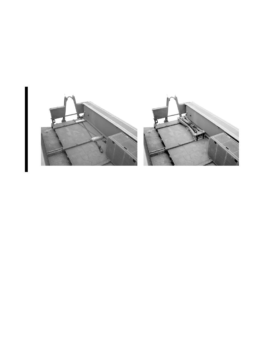
Fold in the arms of the module lifting beam and secure with the shootbolts.
11.15.4.7
Crane in the module lifting beam, positioning it as close to the hook frame as
possible and centrally between the (launch beam) spacers of the adapters. Lower
onto the dunnage. Ensure that it does not sit on the lifting hooks attached to the
ends of the arms. To prevent this, lift the hooks clear before lowering.
Figure 11. 118 Bridge Module Lifter Folded and in Position on LVT Flatrack
11.15.4.8
Disconnect the 2-meter lifting sling from the module lifting beam.
11.15.4.9
Place the lifting beam and secure using the two previously placed straps which pass
beneath the adapters.
11.15.4.10 Place two launch beams onto the flatrack, one positioned on the outside, the other
next to it, adjacent to the previously installed BII straps and basket. Locate the
launch beams in between the spacer blocks on the adapters and close against the
end wall of the flatrack.
11.15.4.11 Place a third launch beam on to the flatrack ensuring that it does not foul the module
lifting beam or basket loads.
11.15.4.12 Place four intermediate flatrack adapters across the launch beams at the positions
shown. Load the remaining four launch beams onto these adapters.
11-122 Change 1


