
TM 5-5420-280-23&P
0024 00
BRIDGE UPPER COUPLING LOCK LEVER, RECEPTACLE, AND LOCKING MECHANISM
MAINTENANCE (Contd)
ADJUSTMENT
NOTE
Perform adjustment with bridge halves uncoupled.
Ensure that all mounting hardware is tightened to metric
standards unless otherwise noted. Refer to metric torque limits in
Perform step 1 if locknuts holding support bracket are not loose.
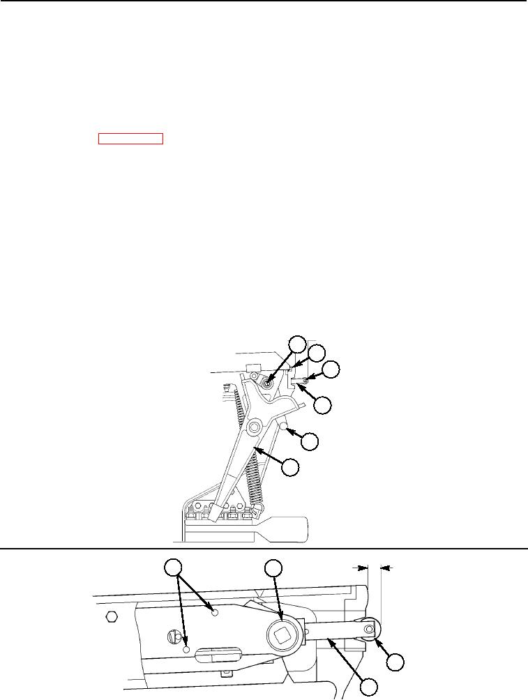
1. Loosen four locknuts (10).
2. Position locking mechanism (1) in unlock position and adjust locking mechanism (1) until roller
wheel (3) on plunger (4) is 0.540 in. (13.7 mm) out from upper crossforce coupling (2). Tighten four
screws (7).
3. Hold remote control lever (6) and push in on roller wheel (3) on plunger (4), lock lever (5) will move to
lock position.
4. Adjust lock lever support bracket (11) until inside of lock lever pins (5) are 0.12 in. (3.04 mm) from
upper crossforce coupling (2). Tighten four locknuts (10).
5. Check clearance between top of lock lever (5) and bridge deck. There must be 0.12 in. (3.04 mm) with
needle cam follower (9) on lever (8) in the lowest position on remote control lever (6).
1
2
3
4
5
6
7
1
0.540 in.
(13.7 mm)
3
4
Change 1
0024 00-12