
TM 5-5420-280-23&P
0024 00
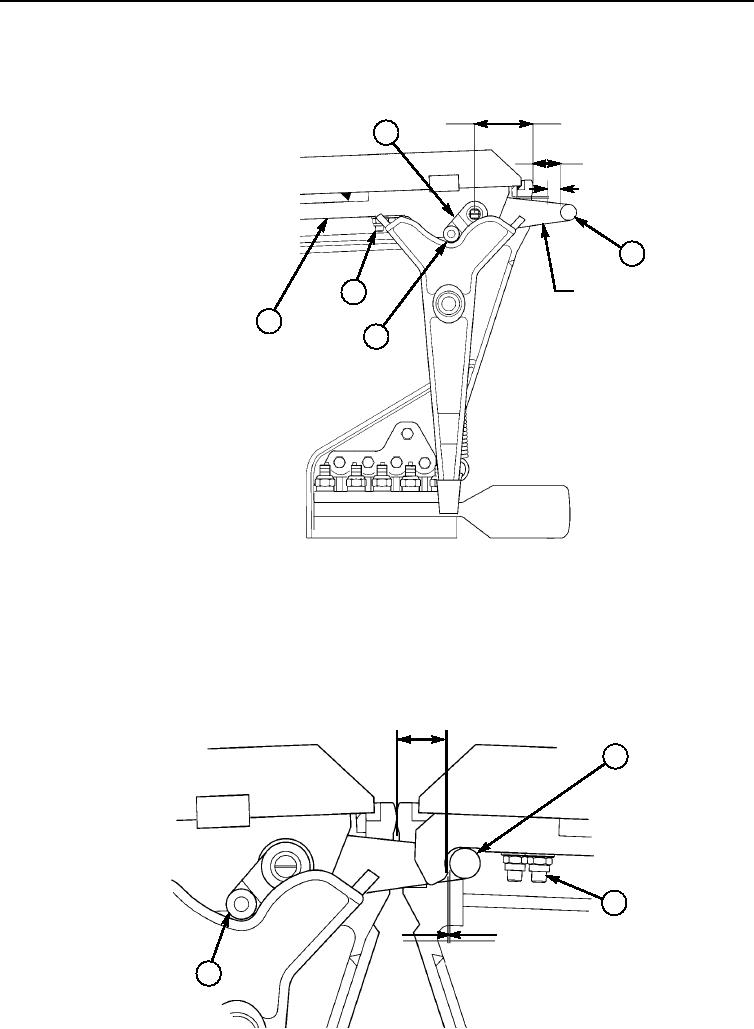
BRIDGE UPPER COUPLING LOCK LEVER, RECEPTACLE, AND LOCKING MECHANISM
MAINTENANCE (Contd)
3.60 in.
(9.14 cm)
8
1.70 in.
(4.32 cm)
0.12 in.
(3.04 mm)
5
LOCK POSITION
10
11
9
NOTE
Perform adjustment with bridge halves coupled.
6. Check distance from upper crossforce couplings (2) to center of lock lever (5). There must be 2.09 in.
(5.3 cm) at this point.
7. Check clearance between lock lever pin (5) and locking point with lock lever (5) in lock position. There
must be 0.197 in. (5.00 mm) when locked.
1.70 in.
(4.32 cm)
5
10
0.197 in.
(5.00 mm)
9
END OF WORK PACKAGE
0024 00-13/14 blank
Change 1