TM 5-5420-280-23&P
0104 00
HYDRAULIC PUMP ASSEMBLY, DRIVE GEARS, AND ADAPTER REPLACEMENT (Contd)
INSTALLATION
NOTE
Apply a light coat of hydraulic oil on O-rings at installation.
1.
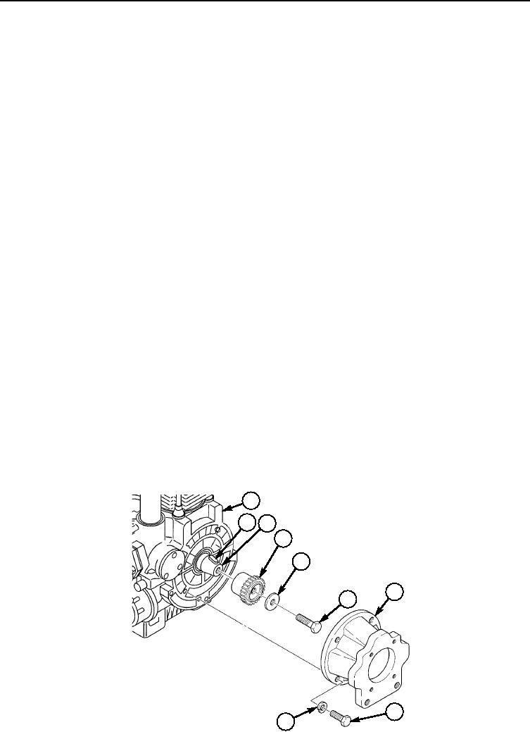
Install engine drive gear (4) on key (2) and engine crankshaft (3) with washer (5), and screw (6).
2.
Install adapter housing (7) on engine (1) with five new lockwashers (9) and screws (8).
3.
Install pump drive gear (12) on key (14) and pump shaft (13) with washer (11) and new
locknut (10).
4.
Install elbow (27) on pump adapter (30) and tighten nut (28).
5.
Install adapter (30) on side of pump (39) with new O-ring (31), four new lockwashers (21), and two
screws (22) and (29).
6.
Install tee fitting (25) on elbow (27) and tighten nut (26).
7.
Install adapter (23) on tee fitting (25) and tighten nut (24).
8.
Install pump adapter (41) on side of pump (39) with new O-ring (40), four new lockwashers (42), and
two screws (43) and (44).
9.
Install tee fitting (35) on pump adapter (41) and tighten nut (38).
10.
Install elbow (37) on tee fitting (35) and tighten nut (36).
11.
Install tube (33) on tee fitting (35) and tighten nut (34).
12.
Install two new O-rings (16) and adapters (20) on shutoff valve (15).
13.
Install shutoff valve (15) on tube (33) and tighten nut (32).
14.
Install bypass tube (17) on tee fitting adapter (23) and shutoff valve adapter (20) and tighten
nuts (18) and (19).
15.
Install drive coupling (49) on engine drive gear (4).
16.
Align pump drive gear (12) with drive coupling (49) and install pump (39) on adapter housing (7)
with four new lockwashers (48) and screws (47).
17.
Install oil pressure hose (46) on elbow (37) of pump (39).
18.
Install oil supply hose (45) on tee fitting (25) of pump (39).
NOTE
The pallet hydraulic system is self-bleeding, and with the exception
of the telescopic tube hydraulic cylinders, there is no requirement
for bleeding air from the system.
19.
Start engine, operate system, and check all pump lines for leaks. Refer to TM 5-5420-280-10.
1
2
3
4
5
7
6
8
9
0104 00-4

