TM 55-1945-205-10-2
0009 00 3/4 blank
0009 00
d.
Remove the crowbar (2).
e.
Drive the guillotine bar (5) back into stowed position using a sledgehammer to secure the male connector
pins (8) in the fully extended position.
3.
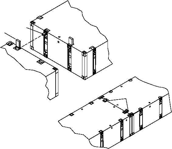
Position the modules to be connected so that the male connector pins (9) and female (1) connectors are aligned.
4.
Using a sledgehammer, drive each female guillotine connector (1) down.
5.
If the female guillotine does not close completely, lift the male guillotine bar two to three in. and repeat step three.
6.
If female guillotine does not close completely, lift male guillotine bar two to three inches and repeat step 3.
END OF WORK PACKAGE
8
1
1