TM 55-1945-205-10-4
0007 00 1
0007 00
OPERATOR MAINTENANCE
FLOATING CAUSEWAY
DESCRIPTION AND USE OF OPERATOR
CONTROLS AND INDICATORS
GENERAL
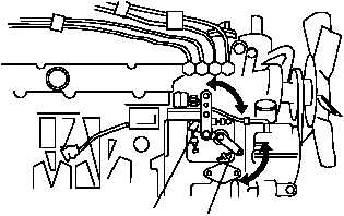
The following paragraphs contain illustrations that show the location of each control and indicator for operation of
the FC platform and installed items of equipment. Each control and indicator is clearly labeled as it appears on the
equipment. Find numbers on the illustration are keyed to the tabular listing which contains the name, based on the
equipment markings and the functional description of each control and indicator.
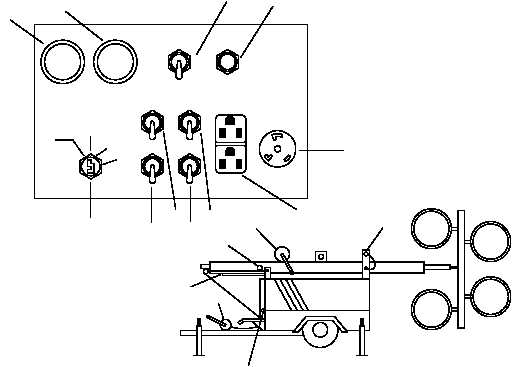
LIGHT TOWER CONTROLS AND INDICATORS
Table 1 describes the controls and indicators for the light tower.
HOURMETER
OFF
RUN
START
PRE
HEAT
FUEL LEVEL
MAIN
BREAKER
RECEPTACLE
120 V 20A
RECEPTACLE
240 V 20A
PUSH TO
RESET
LAMP
2
LAMP
1
LAMP
4
LAMP
3
1
2
4
9
11
3
7
5
8
6
10
14
17
13
12
15
16
18
19