TM 55-1945-205-24-2
0316 00 6
0316 00
5.
Position new float (11) on carburetor body (18) so hinge pin hole aligns with mounting holes in housing.
6.
Install new float hinge pin (10).
7.
Using fixed jet screwdriver, install orifice (7) in float housing (9).
8.
Install new preformed packing (6) on drain plug (5).
9.
Install drain plug (5) in float chamber (9).
10. Install spring (16) on needle valve (15).
11. Using fixed jet screwdriver, install needle valve (15) and spring (16) in carburetor body. Screw orifice into body
slowly, until it touches valve seat. Then back needle valve (15) out 2¾ turns.
12. Install new carburetor cover gasket (4) on body (9), matching mounting holes and shape.
13. Install carburetor cover (2).
WARNING
14. Apply sealing compound to threads of four carburetor cover screws (3) and tighten.
15. Using a torque wrench, tighten screws (3) in criss-cross configuration, to 15 - 22 in. lbs (1.6 - 2.4 N-m).
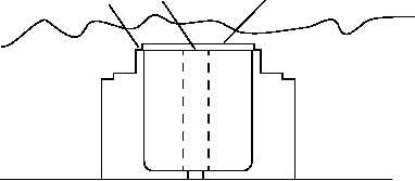
16. To adjust float level, turn carburetor assembly onto cover and proceed as follows:
a.
Position float gage (19) on surface of float bowl (20), so float surface (21) and gage upper and lower surfaces
can be observed.
b.
Adjust float so float surface (21) touches lower gage surface, but not upper gage surface.
20
19
21