
TM 5-5420-202-34
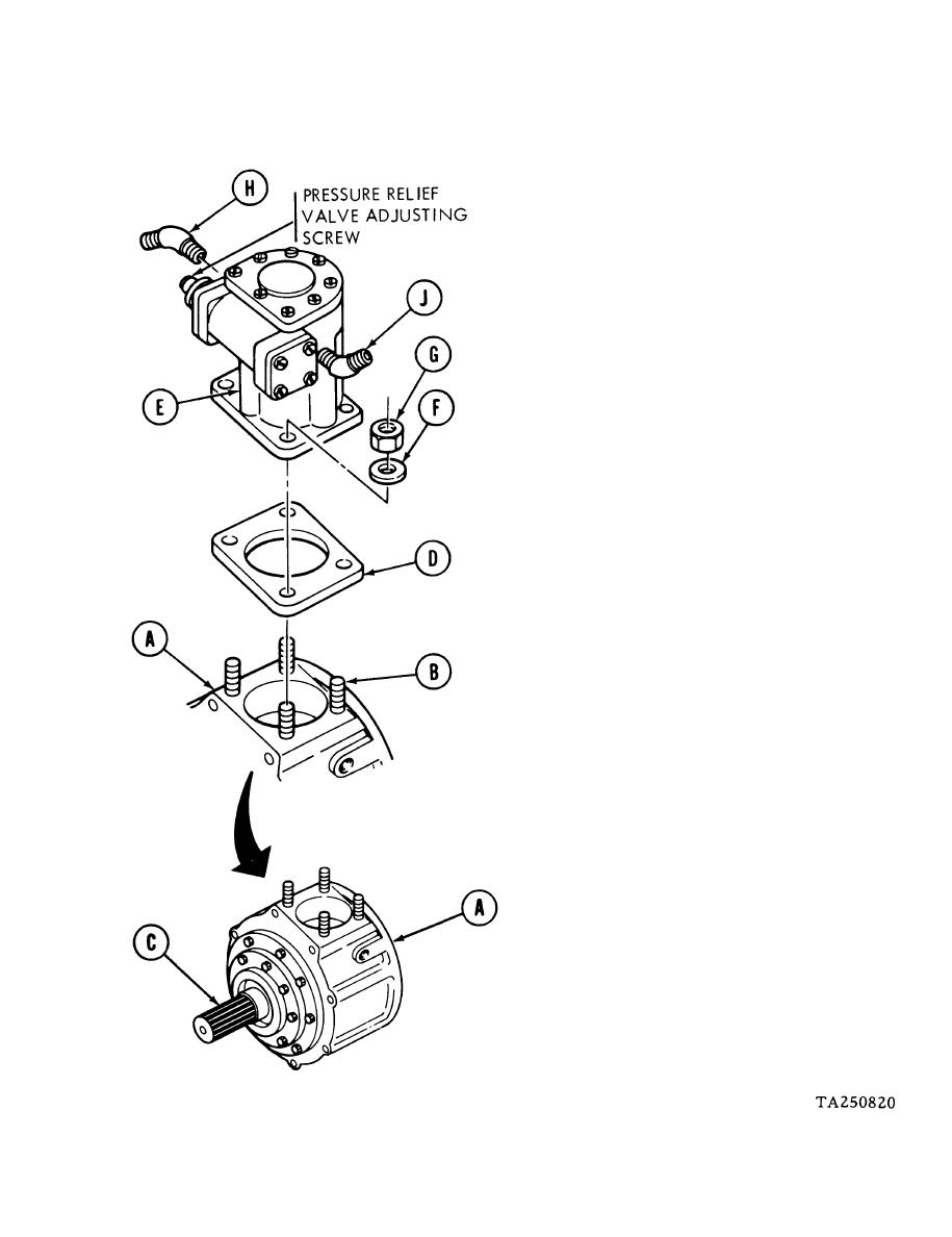
POWER TAKEOFF REPLACEMENT (Sheet 4 of 8)
INSTALLATION:
Place power takeoff (A) on bench with
1.
fuel pump mounting studs (B) facing
upward and splined output shaft (C)
pointing toward you.
Place gasket (D) in position over studs
2.
(B).
3.
Place fuel pump (E) in position on studs
(B). Pump must be positioned so that
pump pressure relief valve adjusting
screw is on your left as you face it.
4.
Using 1/2 inch wrench, secure pump
(E) to mounting studs (B) with four washers
(F) and four nuts (G).
5.
Carefully thread two 45-degree elbows
(H) and (J) into inlet and outlet ports
of pump (E) until elbows are hand
tight.
6.
Wrap elbows (H) and (J) with clean
rags to protect threads.
7.
Using pipe wrench, carefully tighten
elbows (H) and (J) so that they are alined
with long axis of pump (E). Elbow (H)
must point downward and elbow (J) must
point upward.
Go on to Sheet 5
3-9

