
TM 5-5420-202-34
ACCELERATOR CONTROL LINKAGE ASSEMBLY REPLACEMENT (Sheet 6 of 6)
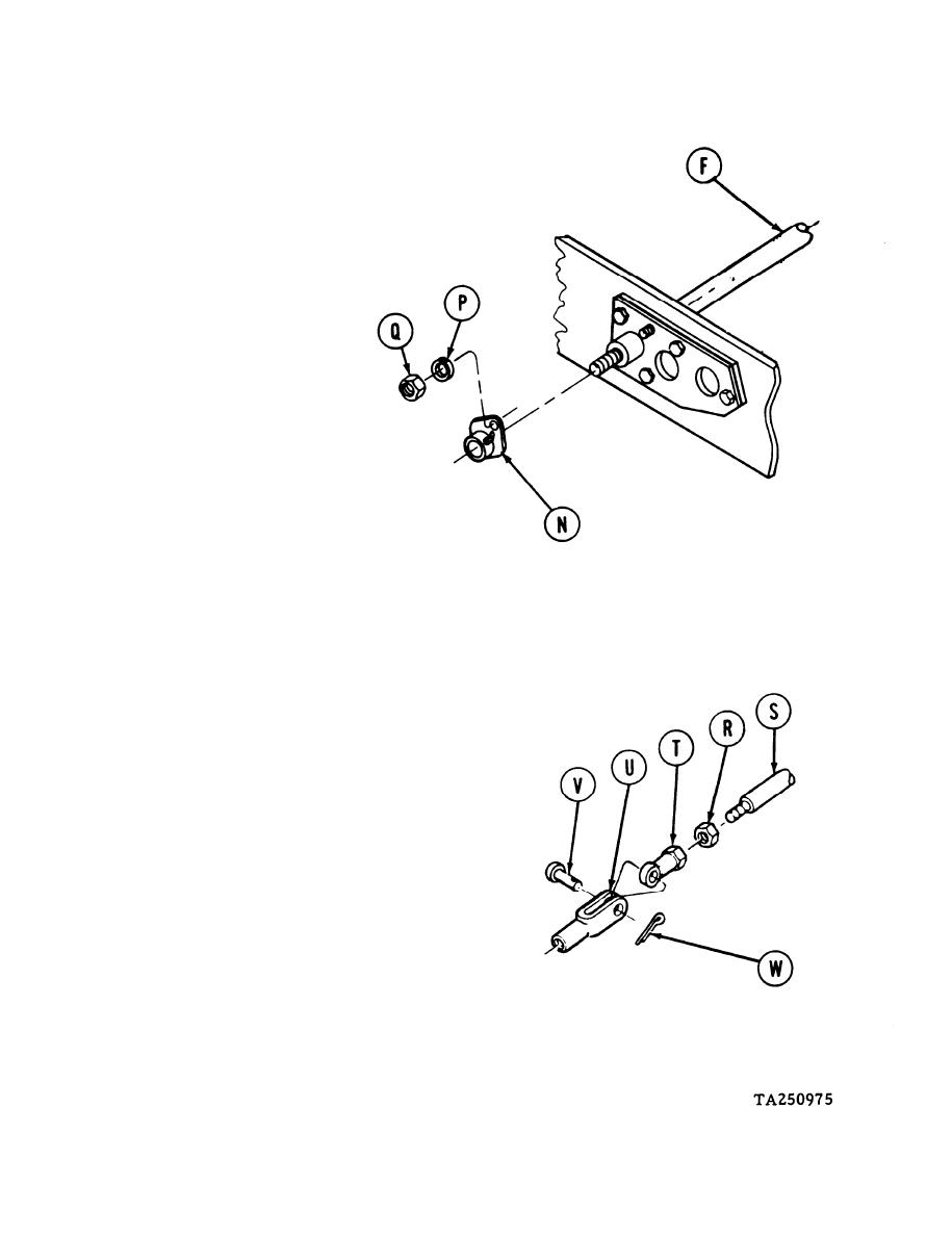
11.
Aline flange (N) over studs of tube assembly
(F) with grease fitting facing upward.
12.
Using 9/16 inch socket, install two
lockwashers (P) and nuts (Q) on studs.
13.
Using 1/2 inch wrench, install jamnut
(R) on tube (S).
14.
Using 7/16 inch wrench, install rod end
(T) on tube (S).
15.
Continue to tighten rod end (T) on tube
(S) until hole in clevis (U) alines with
hole in rod end (T).
16.
Using pliers, install straight pin (V).
17.
Using pliers, install new cotter pin (W).
18.
Using 1/2 inch wrench, tighten nut (R)
against rod end (T).
19.
Install powerplant (TM 5-5420-202-20).
Install torsion bars 5L and 5R (TM 5-5420-
20.
202-20).
21.
Install floor access plate under operator's
seat (TM 5-5420-202-20).
End of Task
4-98

