
TM 5-5420-226-20-3
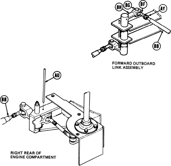
SHIFT LINKAGE ADJUSTMENT (Sheet 17 of 28)
NOTE
Do not allow shifting rod (BB) to turn while doing
step 87. Shifting rod (BB) is made up of more than
one piece and may come apart if allowed to turn.
Using 9/16 inch wrench, adjust shifting rod
87.
bearing end (BF) by turning clockwise or
counterclockwise until screw (BG) will drop
freely through clevis (BH) and shifting rod
bearing end (BF).
Using 9/16 inch wrench, install screw (BG).
88.
Holding rod bearing end (BF) with 9/16 inch
89.
wrench, use torque wrench and 9/16 inch crow-
foot adapter to tighten jamnut (AY) to 16-18
lb-ft (22-24 Nm).
90.
Remove locating pin (AU) from alinement
holes.
91.
Using torque wrench and 9/16 inch socket,
tighten screw (BG) to 16-18 lb-ft (22-24 Nm)
and go on to step 102.
Go on to Sheet 18
TA169070
11-69

