
TM 5-5420-226-20-3
BRAKE SWITCH (STOPLIGHT) REPLACEMENT (Sheet 3 of 4)
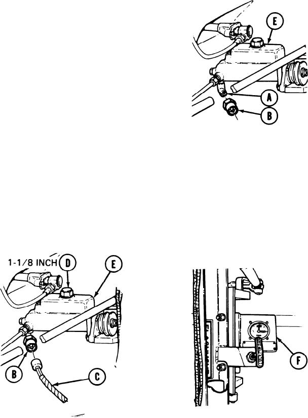
INSTALLATION:
1.
Using fingers, remove plug from elbow
(A).
Using 1 inch deep style socket, install
2.
stoplight switch (B).
Using fingers, connect electrical con-
3.
nector (C) to stoplight switch (B).
Using 1-1/8 inch socket, remove filler
4.
cap (D).
Using funnel, fill master cylinder (E)
5.
with brake fluid to 1/4 inch from top
of opening.
Using 1-1/8 inch socket, install filler
6.
cap (D).
Press (not pump) brake pedal to ensure a pressure of 800 to 1000 psi (see gage F) is
7.
maintained without spongy pedal movement.
Place MASTER BATTERY switch in ON position.
8.
While pressing brake pedal, have second person check that both brake lights light up.
9.
10.
Place MASTER BATTERY switch in OFF position.
TA169162

