
TM 5-5420-226-20-3
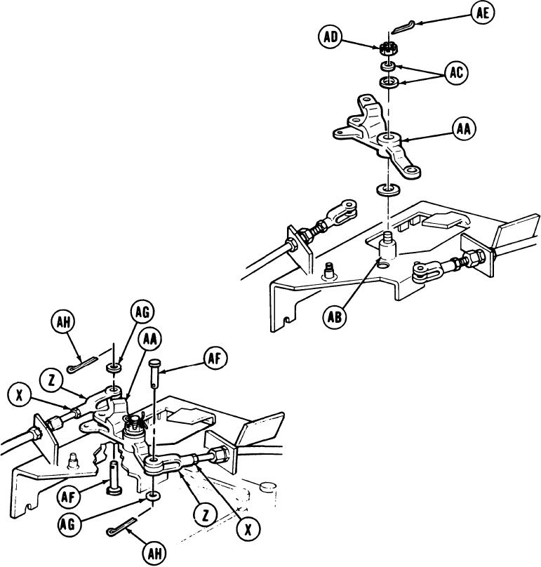
PARKING BRAKE CONTROL ASSEMBLY (ENGINE COMPARTMENT) REPLACEMENT (Sheet 13 of 15)
19.
Install bellcrank (AA) onto stud (AB).
20.
Install two flat washers (AC) onto stud
(AB).
21.
Install nut (AD) onto stud. Using 9/16
inch socket and torque wrench, tighten
nut (AD) to 19-21 lb-ft (26-34 NZm).
22.
Back off nut (AD) to aline slots in nut
with hole in stud (AB).
23.
Install new cotter pin (AE) through stud
(AB) hole. Using long nosed pliers, bend
cotter pin (AE) to prevent it from falling
out.
24.
Position both clevises (Z) to bellcrank
(AA).
25.
Install pins (AF) and washers (AG) to
secure clevis (Z) to bellcrank (AA).
26.
Install new cotter pins (AH) through hole
in pins (AF).
27.
Using long nosed pliers, bend cotter pins
(AH) to prevent them from falling out.
28.
Using screwdriver to hold clevis (Z), use
9/16 inch crowfoot and torque wrench
to tighten nuts (X) to 28-30 lb-ft
(38-41 Nm).
Go on to Sheet 14
TA169243
13-119

