
TM 5-5420-228-24
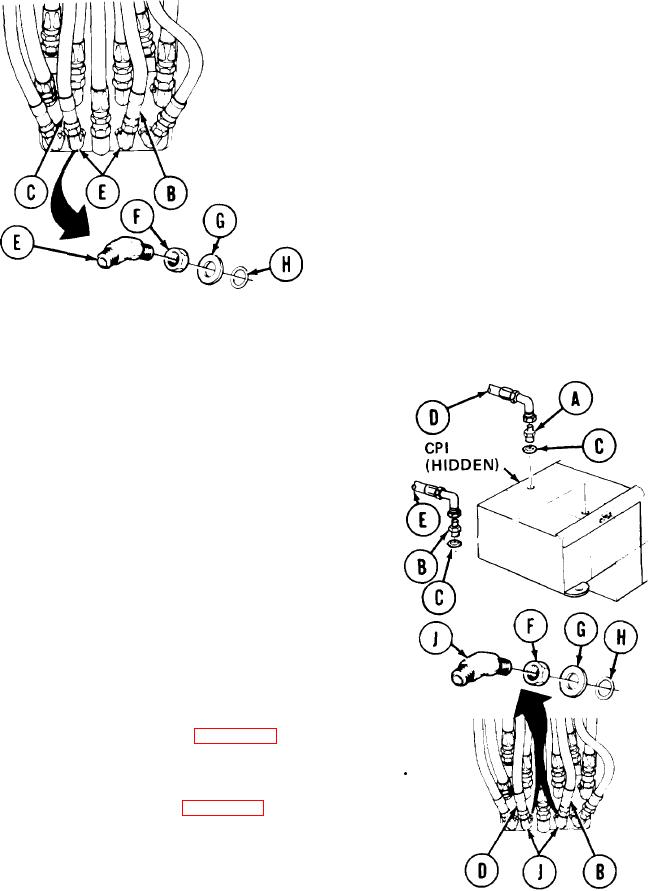
EJECTION CYLINDER HOSE ASSEMBLIES (CP1 AND CP2) AND HYDRAULIC REPLACEMENT
(Sheet 2 of 2)
Using adjustable wrench to hold elbows (E),
3.
use 7/8 inch wrench to remove hose
assemblies "CP1" (B) and "CP2" (C).
4.
Using adjustable wrench to hold elbows (E),
use 7/8 inch wrench to loosen elbow nuts
(F).
5.
Using adjustable wrench, remove elbows
(E), flat washers (G), nut (F), and
Throw
packings (H).
preformed
preformed packings (H) away.
INSTALLATION:
NOTE
Before installation, use pipe tape on all male threads. Start on second thread so tape
will not enter hydraulic system.
Using 1-1/4 inch wrench, install adapters (A)
1.
and (B) and new preformed packings (C).
2.
Using 1-1/4 inch wrench on adapters (A) and
(B), use 11/16 inch wrench to install hose
assemblies "CP1" (D) and "CP2" (E).
Manually install nuts (F), flat washers
3.
(G), and new preformed packings (H) on
elbows (J).
4.
Manually install elbows (J) in vehicle and
aline elbows a shown.
Using adjustable wrench on elbows (J), use
5.
7/8 inch wrench to tighten elbow nuts (F).
Using adjustable wrench on elbows (J),
6.
use 7/8 inch wrench to install hose
assemblies "CP1" (D) and "CP2" (E).
7.
Bleed hydraulic system (page 3-72).
8.
Check for hydraulic leaks and correct as necessary
Install front quadrant (page 3-46).
9.
Service hydraulic reservoir (LO 5-5420-202-12).
10.
TA251576
End of Task
3-179

