
TM 5-5420-228-24
VALVE BANK ASSEMBLY AND BRACKETS REPLACEMENT (Sheet 6 of 17)
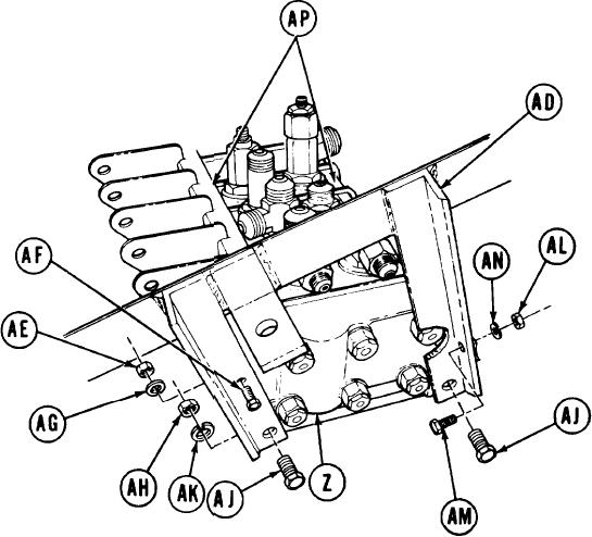
Using 7/16 inch wrench to hold nut
24.
(AE), use 7/16 inch socket to loosen
screw (AF).
25.
Manually remove screw (AF), nut (AE), and
lock washer (AG). Throw lock washer
(AG) away.
26.
Using 3/4 inch wrench to hold nuts
(AH), use 3/4 inch socket to loosen
screws (AJ).
27.
Manually remove two screws (AJ), nuts
(AH), and lockwashers (AK). Throw
lockwashers (AK) away.
Using 1/2 inch wrench to hold nut (AL), use 1/2 inch socket to loosen screw (AM).
28.
29.
Manually remove screw (AM), nut (AL), and lockwasher (AN). Throw lockwasher (AN)
away.
Manually remove bracket (AD) from valve bank (Z).
30.
31.
Repeat steps 24 thru 30 for other end of valve bank (Z).
32.
Manually remove identification plates (AP).
Go on to Sheet 7
TA251707
4-58

