
TM 5-5420-228-24
HEU VALVE BANK PREFORMED PACKINGS AND FITTINGS REPLACEMENT
(Sheet 1 of 2)
PROCEDURE INDEX
Procedures
Page
Removal
Installation
TOOLS:
12 inch adjustable wrench
SUPPLIES:
Rags (Item 12, Appendix D)
Drip pans (Suitable containers)
Gloves (Item 27, Appendix D)
Preformed packings (as required)
Protective caps and plugs
REFERENCE: LO-12
PRELIMINARY PROCEDURE:
Appropriate hose removed (page 3-70.1)
Hydraulic pressure reduced (page 3-71)
REMOVAL:
NOTE
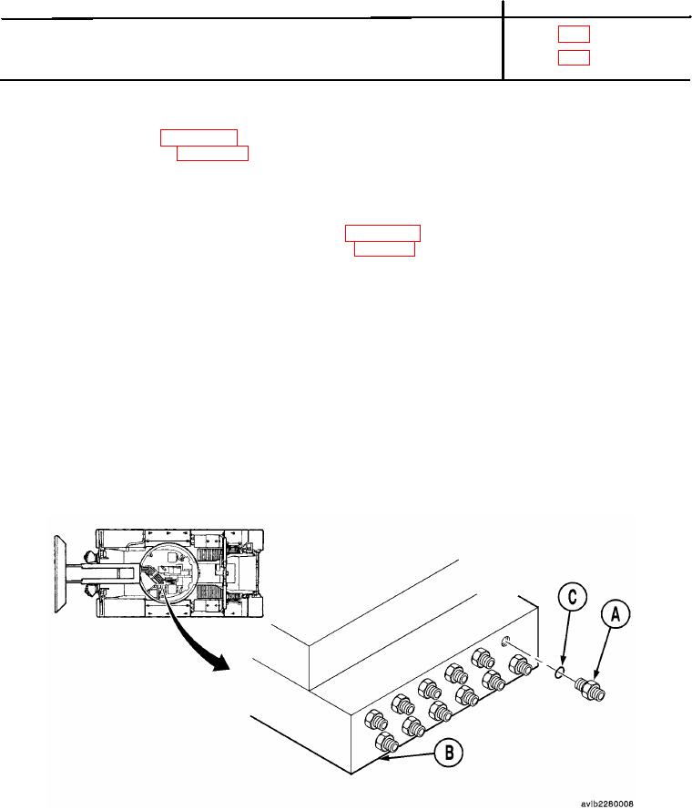
Use this procedure to remove any of the fittings or elbows located on the
manual valve bank assembly. Rear fitting is shown.
It may be necessary to remove one or more fittings for access.
Cap or plug all hydraulic lines or openings when removing.
1.
Using a 12 inch adjustable wrench, remove adapter (A) from valve bank (B) then remove preformed packing (C).
2.
After preformed packings and adapters are removed from the back of valve bank, continue to the front of valve
bank removing preformed packings and adapters.
Go on to Sheet 2

