TM 5-1940-322-24
0156 00
CRANKSHAFT AND CRANKSHAFT GEAR REPLACEMENT (Contd)
INSTALLATION
CAUTION
Use only hand force to push the piston cooling nozzle in place. If
driven with a hammer, it will cause damage to the piston cooling
nozzle.
NOTE
Install cooling nozzles even with or slightly below the saddle
surface.
1.
Using center punch, push piston cooling nozzle (5) in cylinder block (3).
CAUTION
Ensure saddle surface is clean and dry. Failure to comply may
cause engine damage.
2.
Install crankshaft gear (8) on crankshaft (4).
3.
Install upper main bearing halves (9) in cylinder block (3).
4.
Install upper combination thrust main bearing (10) in cylinder block (3).
5.
Apply coat of lubriplate to six bearings (9) and upper combination thrust main bearing (10).
WARNING
Do not detach lifting device from crankshaft until all crankshaft
weight is equally distributed and stable. An improperly supported
crankshaft may cause injury to personnel.
CAUTION
Crankshaft must be lowered on the bearings straight to prevent
damage to thrust bearings.
6.
Using lifting device, install crankshaft (4) on six bearings (9) and upper combination thrust main
bearing (10) in cylinder block (3).
7.
Install ring dowels (6) in main bearing caps (2).
8.
Install six lower main bearing halves (7) and lower combination thrust main bearing (11) in main
bearing caps (2).
9.
Apply coat of lubriplate on lower main bearings (7) and lower combination thrust main bearing (11).
NOTE
Numbers on the main bearing caps face the oil cooler side of the
engine with number one at the front of the engine.
10.
Apply coat of engine oil to threads of bolts (1).
11.
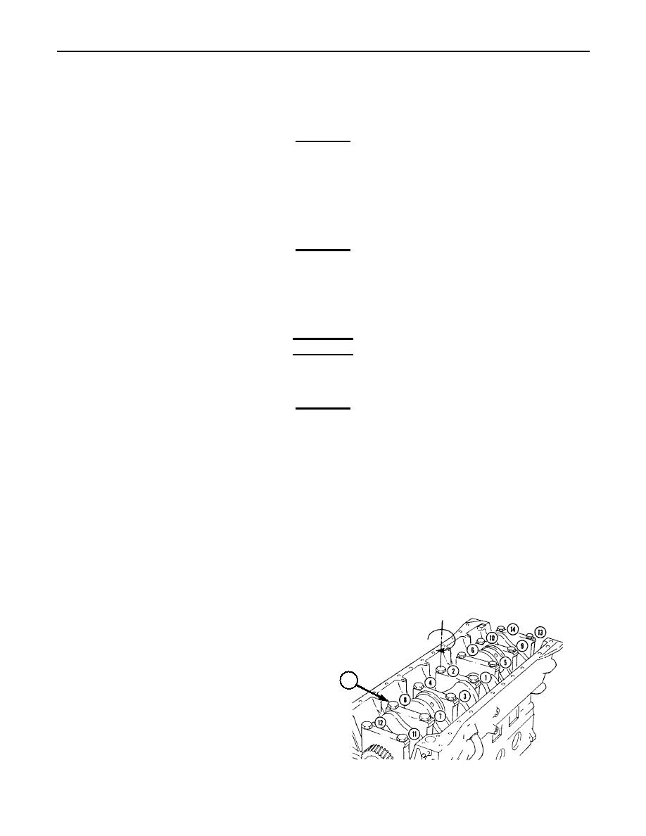
Install seven main bearing caps (2) on cylinder block (3) with fourteen bolts (1). Tighten bolts (1)
evenly in sequence (shown in figure below).
a. Tighten bolts (1) in sequence to 44 lb-ft (60 Nm).
b. Tighten bolts (1) in sequence to 88 lb-ft (119 Nm).
c. Tighten bolts (1) in sequence to 129 lb-ft (176 Nm).
1
0156 00-4


