• Home
  • Download PDF
  • Order CD-ROM
  • Order in Print
MULTIPLE FLUID PRESSURE LINE CONNECTOR REPLACEMENT (Sheet 4 of 6)
MULTIPLE FLUID PRESSURE LINE CONNECTOR REPLACEMENT (Sheet 6 of 6)

Maintenance Manual For Launcher,Tank Chassis Transporting: For Bridge Armored-Vehicle-Launched: Scissoring-Type; Class 60 And 70 -2 Page Navigation
  145    146    147    148    149  150  151    152    153    154    155  
img
TM 5-5420-202-20-2
MULTIPLE FLUID PRESSURE LINE CONNECTOR REPLACEMENT (Sheet 5 of 6)
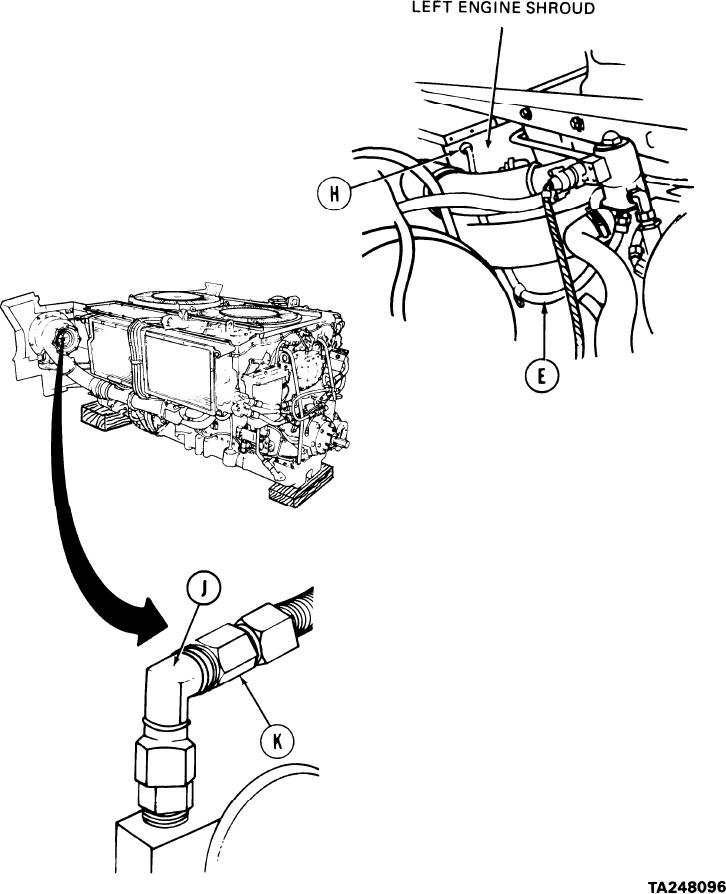
8.
Position hose (E) so that free end passes
through left engine shroud. Using fingers
a n d flat-tip screwdriver, position grommet
(H) over hose and into shroud.
Using 1/2 inch wrench and 1/2 inch socket,
9.
secure each hose with loop clamp.
10. Using 11/16 inch wrench, connect hose
connector (K) to elbow (J) on right
turbosupercharger.
11. Repeat step 10 on left turbosupercharger
to connect hose (E).
Go on to Sheet 6
6-105


Privacy Statement
Press Release
Contact

© Copyright Integrated Publishing, Inc.. All Rights Reserved.