
TM 5-5420-202-20-2
POWERPLANT LEFT BANK OIL COOLER FRAME AND BRACKETS REPLACEMENT (Sheet 7 of 9)
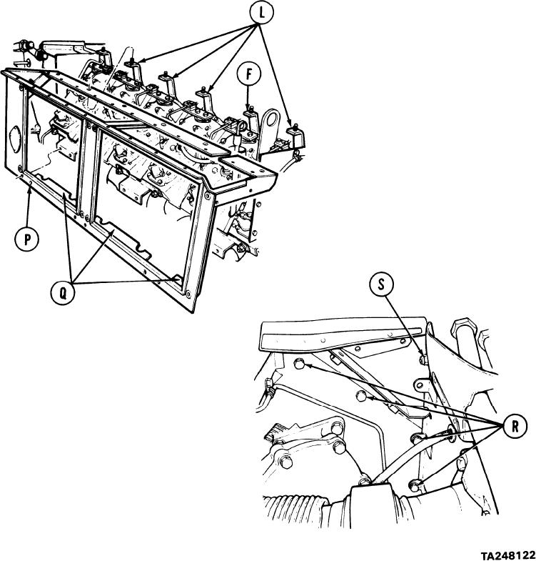
NOTE
It may be necessary to puII frame (P) out and depress
three flanges (Q) on frame bottom during installation
to clear protruding obstacles on the engine. It may
be necessary to loosen and move brackets (B, F and
L) slightly before oil cooler support frame can be
installed.
12. Install oil cooler support frame.
13. Using alining punch, aline screw
holes and, using 1/2 inch socket
with extension, install four screws (R).
14.
Using 1/2 inch socket and 1/2 inch
wrench, install screw and self-locking
nut (S).
Go on to Sheet 8
6-132