
TM 5-5420-202-20-2
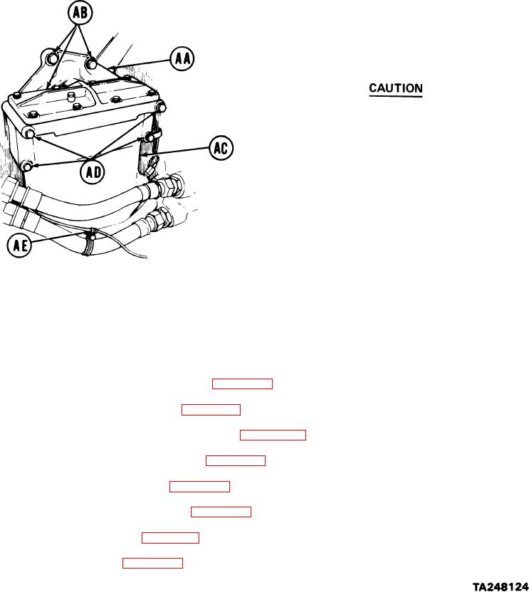
POWERPLANT LEFT BANK OIL COOLER FRAME AND BRACKETS REPLACEMENT (Sheet 9 of 9)
22.
Place mounting bracket (AA) in position and,
using 5/8 inch socket, tighten three screws
(AB).
23.
Position fuel-water separator (AC) to
m o u n t i n g bracket (AA).
Mounting bracket (AA) is made of
aluminum. Overtightening of cap-
screws (AD) could strip threads.
24.
Using 1/2 inch socket, install four
capscrews, lockwashers, and flat
washers (AD).
25.
Using screwdriver and 3/8 inch wrench, install clamp (AE) if removed.
26.
Install transmission left oil cooler (page 6-43).
27.
Install engine left oil cooler (page 6-22).
28.
Install engine access covers (left bank) (page 6-115).
29.
Install engine cooling fan shroud (page 9-51).
30.
Install engine cooling fans (page 9-57).
31.
Install centrifugal fan housing (page 9-65).
32.
Install engine shroud (page 9-31).
33.
Install powerplant (page 5-14).
End
of
Task
6-134