
TM 5-5420-202-20-2
MANIFOLD HEATER FUEL RETURN TUBE ASSEMBLY REPLACEMENT (LEFT AND RIGHT
BANK) (Sheet 3 of 7)
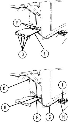
3. Using 1/2inch socket, ratchet, and 1/2
inch wrench, remove four screws and
washers (D) fro m lower engine cooling
fan shroud (E).
4 . Using screwdriver, remove two screws
a n d washers ( F ) f r o m l o w e r e n g i n e
cooling fan shroud (E).
( L e f t screw is
hidden. You will have to feel for it.)
NOTE
The engine cooling fan shroud (E)
must be slightly displaced in step 5 to
allow clearance for removal of the
manifold heater return tube (C).
5. Using hammer handle, tap on bottom of
engine cooling fan shroud (E). Second
technician, using screwdriver, pry up on
front lip of cooling fan shroud and slightly
displace it.
6. Using fingers, remove grommet (G) from
tube assembly (C).
7. Using 9/16 inch wrench, remove line nut
of tube assembly (C) from elbow (H) on
manifold heater (J).
TA248392
Go on to Sheet 4
7-268