
TM 5-5420-202-20-2
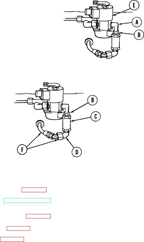
CHECK VALVE (MANIFOLD HEATER - RETURN FUEL) REPLACEMENT (Sheet 3 of 3)
INSTALLATION:
Coat threads of elbow (A), nipple (B), check valve (C), and elbow (D) with sealing
1.
compound.
2.
Using 9/16 inch wrench, install
elbow (A) in solenoid valve (E) in
position shown.
Install nipple (B) to elbow (A).
3.
4.
Install check valve (C) to nipple (B).
5.
Install elbow (D) to check valve (C).
6.
Using proper wrenches, tighten and aline parts (B), (C), and (D) to be able to connect hose
assembly (F) to elbow (D).
7.
Connect hose assembly (F) to elbow (D).
8.
Using 7/16 inch and 9/16 inch wrenches, tighten hose assembly (F) connection to elbow (D).
Connect engine ground hop (page 5-25). DO NOT start engine.
9.
10.
Operate purge pump (TM 5-5420-202-10) and check for leaks. If leaks are found, tighten
connections as required.
11.
Disconnect engine ground hop (page 5-40).
12.
Install engine shroud (page 9-31).
13.
Install powerplant (page 5-14).
TA248389
End of Task
7-265