
TM 5-5420-202-20-3
INTERCONNECTING BOX ASSEMBLY REPAIR (Sheet 5 of 8)
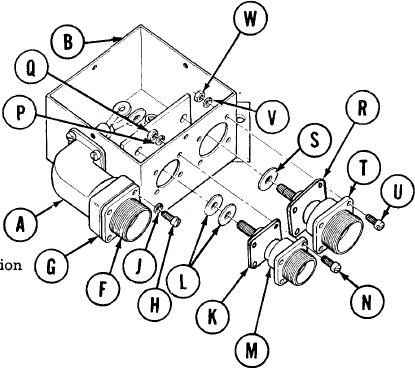
Using screwdriver, install four screws
5.
(H) and lockwashers (J) securing lead
assembly (F) and gasket (G) to elbow
(A).
6. Place gasket (K) and flat washer (L)
on receptacle assembly (M).
Place receptacle assembly (M) in posit
on box assembly (B).
Using fingers, install four screws (N),
8.
lockwashers (P), and nuts (Q) securing
receptacle assembly (M) to box assembly
(B).
9. Holding nuts (Q) with 5/16 inch wrench, use screwdriver to tighten four screws (N).
10. Place gasket (R) and flat washer (S) on receptacle assembly (T).
11. Place receptacle assembly (T) in position on box assembly (B).
12. Using fingers, install four screws (U), lockwashers (V), and nuts (W) securing receptacle
assembly (T) to box assembly (B).
13. Holding nuts (W) with 11/32 inch wrench, use screwdriver to tighten four screws (U).
TA249089
Go on to Sheet 6
10-148