
TM 5-5420-202-20-3
INTERCONNECTING BOX ASSEMBLY REPAIR (Sheet 6 of 8)
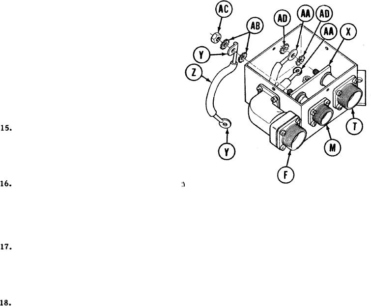
14.
Coat bus bar (X) with Glyptol sealer.
Place bus bar (X) in position on two
receptacle assemblies (M) and (T).
Coat two terminal: (Y) of lead assembly (Z)
and two terminals (AA) of lead assembly (F)
with Glyptol sealer.
Place two lockwashers (AB) and curved terminal (Y) of lead -assembly (Z) in position
on receptacle assembly (M).
Using 7/16 inch wrench, install nut (AC) securing lead assembly (Z) to receptacle
assembly (M).
19. Place two lockwashers (AD) and terminal (AA) of lead assembly (F) in position on receptacle
assembly (T).
TA249090
Go on to Sheet 7
10-149