
TM 5-5420-202-20-3
ENGINE WIRING HARNESS REPLACEMENT (Sheet 10 of 72)
24.
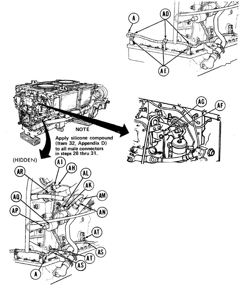
Place wiring harness (A) in position
along bottom of engine.
25.
Place three clamps (AD) in position
around wiring harness (A).
26. Using 7/16 inch socket and wrench,
install three screws, lockwashers
and nuts (AE) securing three
clamps (AD) and wiring harness to
engine
Using slip joint pliers, install
27.
connector (AF) to hour meter (AG).
28.
Connect electrical lead (AH) (CKT 33)
to engine oil temperature transmitter
(AJ).
Connect electrical lead (AK) (CKT 509L)
29.
to engine oil high temperature thermo-
static switch (AL).
Connect electrical lead (AM) (CKT 36)
30.
to engine high oil pressure transmitter
(AN).
Connect electrical lead (AP) (CKT 509L)
31.
to engine low oil pressure switch (AQ).
Place clamp (AR) (hidden) in position
32.
on wiring harness (A).
Using 1/2 inch socket with extension,
33.
install nut securing wiring harness (A)
and clamp (AR).
Place two clamps (AS) in position on
34.
wiring harness (A).
Using 1/2 inch socket, install two screws
35.
and lockwashers (AT).
TA249236
Go on to Sheet 11
10-295