TM 5-5420-202-20-3
PARKING BRAKE PAWL AND BELLCRANK ADJUSTMENT (Sheet 8 of 9)
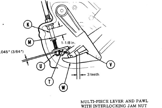
20. In side housing assembly, remove cotter pin (M).
21. Remove 1-1/8 in. gage block from side housing assembly.
22. Lift lever assembly (T) up enough to disengage the lever from the vertical flats on nut
(U). Turn nut (U) on shaft (K) until it just makes contact with lever assembly (T) when
lever is let fully down and is in contact with pawl (V) and pawl is in contact with nonserrated
portion of brake lever (W). When properly adjusted, pawl (V) will be loosely touching
top of brake lever (W).
23. Using pry bar between housing and brake lever (W), move brake lever until the first three
teeth on the brake lever (W) are fully engaged witht he other three teeth on pawl (V).
Note distance between lever assembly (T) and nut (U), nut will clear level assembly
by .045" (3/64") of an inch when proper adjustment has been made. If measurement is
not as stated, go back to step 20 and readjust.
24. Install cotter pin through hole (M).
25. Repeat steps 1-24 for opposite side brake.
Go on to Sheet 9
TA249527
13-143

