
TM 5-5420-202-20-3
PARKING BRAKE PAWL AND BELLCRANK ADJUSTMENT (Sheet 4 of 9)
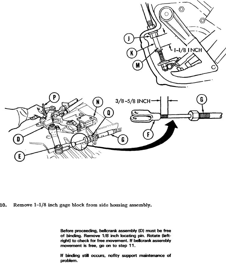
6.
Push/pull cable (K) until 1-1/8 inch gage
block just fits between cotter pin (M)
and sleeve nut (J) (15/16 inch gage block
for one-piece lever and pawl). At top
of transmission? rotate bellcrank assembly
(D) to aline holes in bellcrank (D) and
bracket (N). Insert 1/8 inch locating pin
(P) through holes in bellcrank (D) and bracket
(N).
NOTE
While performing steps 8 and 9, locating pin (P)
must slide up and down freely in alinement holes.
Clevis (F) must be positioned on control (G) so that
3/8 to 5/8 inch thread is remaining.
Using two 15/16 inch wrenches, loosen two nuts (Q) and adjust control assembly (6)
8.
until clevis pin (E) slides freely in the respective holes. If clevis (F) bids at bellcrank,
rotate clevis (F) until bind no longer occurs.
Using two 15/16 inch wrenches, tighten nuts (Q), install devis pin (E) and, using pliers,
9.
install washer and cotter pin on clevis pin (E).
NOTE
Go on to Sheet 5
T A2 4 9 5 2 3
13-139